2- Strength in Overlaps in Purlin and Girts
There are significant differences in the weight of purlins and girts designed by MkaPEB users compared to those designed by a few other engineers. Below, several key sources of these differences are outlined:
Purlins and girts are designed by the engineers as simply supported spans. However, when using cold-formed elements — particularly Z-purlins — they can instead be designed as continuous beams. This continuous configuration typically results in lower maximum bending moments compared to simply supported spans, enabling the use of lighter and more efficient sections.
An important consideration in the design of purlins and girts is the overlap at support locations. In these regions, the strength contributions of the two overlapped purlins or girts are combined. However, most structural analysis and design software cannot model two sections occupying the same physical space, and therefore fail to account for the combined strength at the supports. As a result, the software output neglects this additional capacity, leading to artificially elevated calculated moments at the supports. This, in turn, often compels the designers to find larger, uneconomical, and over-designed sections.
Moreover, when designing purlins and girts as continuous beams, it is important to note that the end spans typically experience higher bending moments than the interior spans. Consequently, the section sizes required for the end spans and intermediate spans may differ. However, in practice, designers often select the same section size for all bays, which results in uneconomical and over-designed sections, particularly for all the interior spans where lighter sections could often suffice.
By enabling users to (1) use cold-formed sections for purlins and girts, (2) design purlins and girts as continuous beams, (3) account for the combined strength of sections in the overlap regions, and (4) select different section sizes for end and intermediate spans, MkaPEB helps them achieve safe yet significantly lighter and more economical designs for purlins and girts.
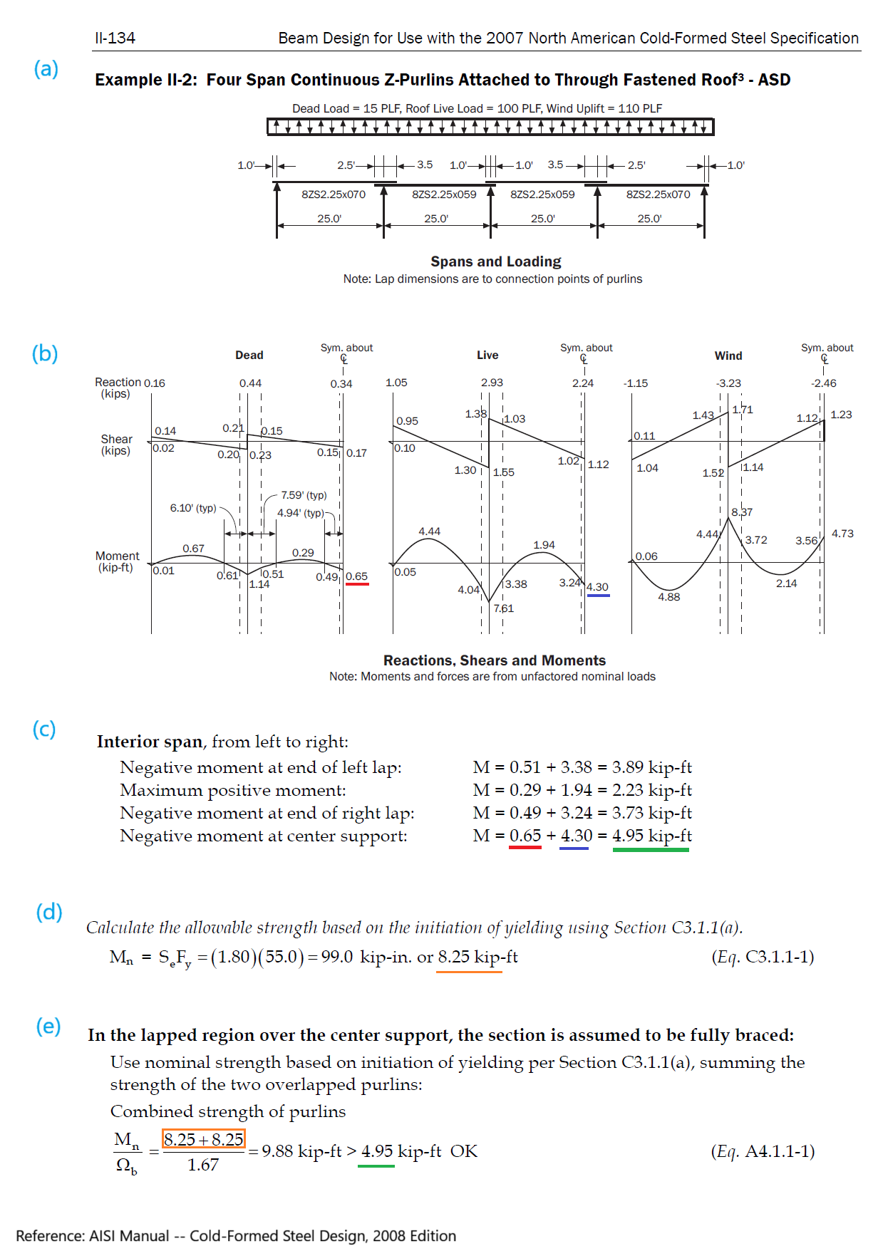
These are not implicit or trivial considerations — they are explicitly addressed in various editions of the AISI Cold-Formed Steel Design Manual. An example from AISI incorporating all the aforementioned points is presented below:
https://scholarsmine.mst.edu/cgi/viewcontent.cgi?article=1159&context=ccfss-aisi-spec (PDF Page: 275/635)
As shown in the AISI example:
1) Cold-formed Z-purlins are used (Figure a).
2) Purlins are continuous beams (Figure a and b).
3) Strength contributions of the two overlapped purlins are combined (Figure e)
4) Different section sizes for end and intermediate spans are selected (Figure a)
Figure below shows how the above mentioned points are included in MkaPEB software.
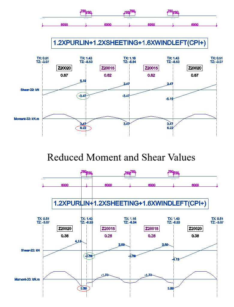
1) Cold-formed Z-purlins are used.
2) Purlins are continuous beams.
3) Strength contributions of the two overlapped purlins are combined:
For this reason:
- The moment values in the right side of the left edge span are decreased from 6.22 kN.m to 3.56 kN.m. Considering that the thicknesses of the sections are different (2 and 1.5 mm), the reduced moment value is calculated as follows:6.22 kN.m X ( 2 mm / (2 mm +1.5 mm )) = 3.56 kN.m
Similarly,
- For the shear of this station, the value is reduced from 3.47 kN to 2.59 kN, as follows: 3.47 kN X ( 2 mm / (2 mm +1.5 mm )) = 2.59 kN
4) Different section sizes for end and intermediate spans are selected (Z20020, Z20015)