Ultimate Bearing Capacity
The stability of a foundation depends primarily on the soil’s ability to support the loads transferred from the superstructure. When the applied stresses exceed the soil’s bearing capacity, failure may occur — potentially compromising both the foundation and the entire structure. The ultimate bearing capacity refers to the maximum pressure the soil can withstand before shear failure occurs.
Using:
1) invalid bearing capacity determination method
2) incorrect determination of the effective foundation area
3) wrong values for the angle of internal friction
can lead some engineers to incorrectly estimate the ultimate bearing capacity, resulting in foundation designs that are significantly smaller than those designed by MKAPEB.
Each point is clearly outlined here:
1) Ultimate Bearing Capacity Determination Methods
In Geo-technical literature, such as Shallow Foundations by Braja M. Das, several empirical and theoretical methods have been proposed to determine the ultimate bearing capacity.
Among them, the Terzaghi and Meyerhof methods are two of the most widely adopted.
1-1- Terzaghi’s Method
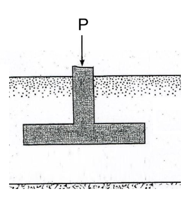
In 1943, Karl Terzaghi expanded on earlier studies (e.g., Prantl, 1921) and developed one of the first bearing capacity equations based on plastic failure theory. His approach makes several key assumptions, including:
- The applied load is purely vertical and centrally applied at the foundation centroid
- No bending moments or load eccentricities are present
- The foundation is shallow and rests on homogeneous, isotropic soil
While effective for simple loading conditions, this method does not reflect the behavior of most modern structures—particularly portal frames and pre-engineered buildings with fixed support, where bending moments are presented.
1-2- Meyerhof’s Method
To address the above-mentioned limitations, Meyerhof proposed an empirical method that accounts for more complex loading conditions. This approach introduced correction factors to the ultimate bearing capacity, including:
- Shape factor: Adjusts for rectangular or circular footing shapes
- Depth factor: Considers the increased shearing resistance with depth
- Inclination factor: Accounts for inclined load application and non-central loading
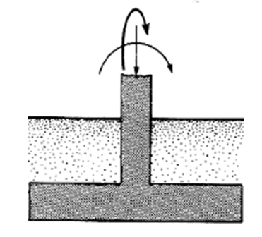
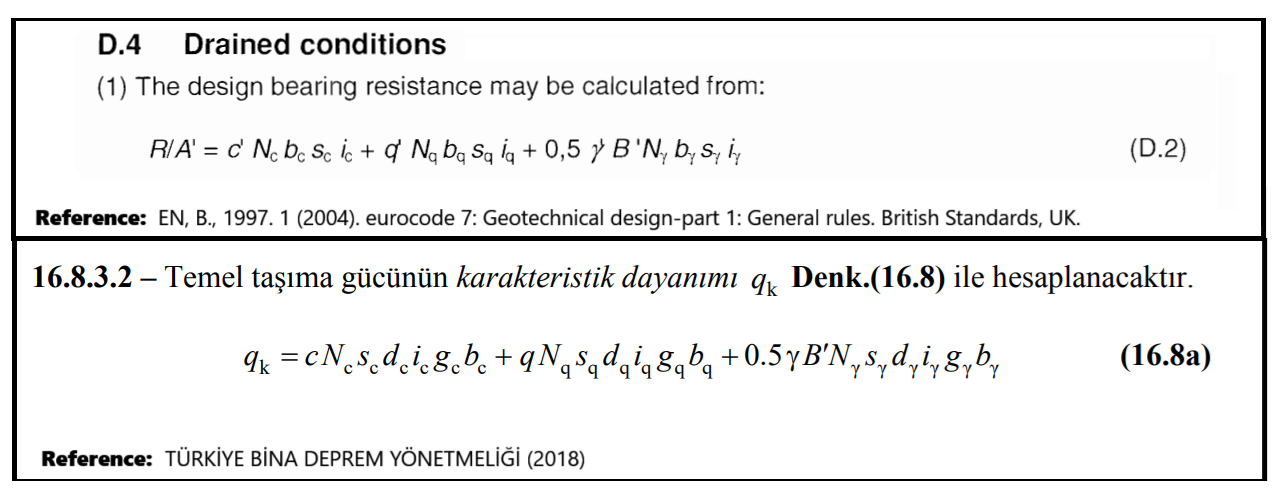
Considering both moments and axial loads, Meyerhof’s approach is the appropriate method for designing most building foundations, particularly for structures such as portal frames and pre-engineered buildings, where combined axial loads and moments typically act at the base. Accordingly, MkaPEB adopts the Meyerhof methodology for calculating the ultimate bearing capacity of foundations.
This aligns with international and national codes such as:
EN 1997-1 (Eurocode 7)
Türkiye Bina Deprem Yönetmeliği (Turkish Seismic Code)
https://www.ngm2016.com/uploads/2/1/7/9/21790806/eurocode_7_-_geotechnical_designen.1997.1.2004.pdf (PDF Page: 160/171)
https://www.resmigazete.gov.tr/eskiler/2018/03/20180318M1-2-1.pdf (PDF Page: 369/416)
Using Terzaghi’s method instead of Meyerhof’s method for determining bearing capacity may lead to significant differences in the calculated ultimate bearing capacity, especially in cases where large moments are present at the base of the building.
2) Effective Foundation Area
In the Meyerhof method, when foundations are subjected to eccentric loading due to the presence of moments, the actual area that effectively resists bearing pressure, referred to as the effective area, is reduced.
This area depends on the magnitude and direction of the load eccentricities, relative to the foundation's length and width.
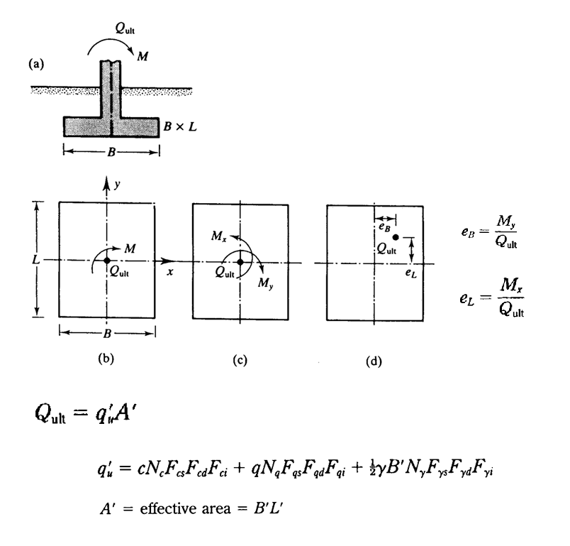
Meyerhof categorized the calculation into four different cases, as shown in the figure, based on the ranges of these eccentricities.
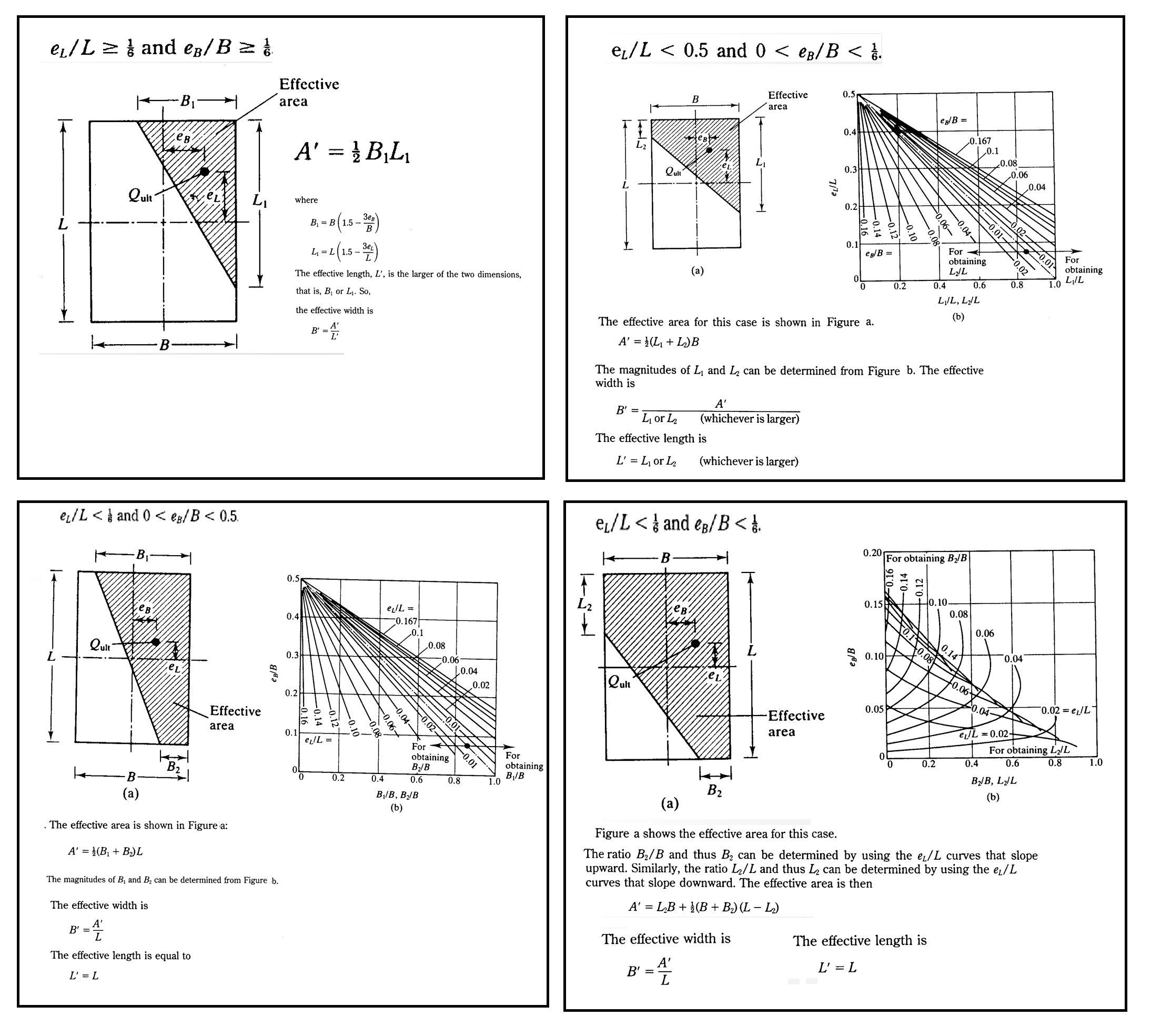
As can be seen, the effective area of a foundation is significantly reduced. MkaPEB incorporates this reduction to accurately account for moments in all load combinations during foundation design. However, ignoring these reductions, as a few foundation designers might do, can lead to significantly smaller but unsafe solutions.
3) Angle of Internal Friction
The friction angle is a key shear strength parameter derived from the Mohr-Coulomb failure criterion. It reflects the soil’s resistance to sliding under shear stress and varies with soil type.
There are several test type to determine the soil friction angle such as: Unconsolidated Undrained (U), Consolidated Undrained (CU) Consolidated Drained (CD) test types.
However these different methods gives different values of friction angle, especially in fine-grained soils like clay.
For example:
- Clay friction angle from CU test: 3° (minimum)
- Clay friction angle from CD test: 20° (minimum)
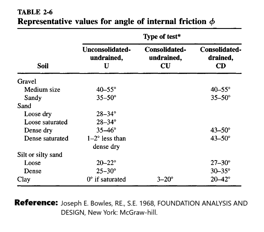
https://cequcest.wordpress.com/wp-content/uploads/2015/09/je-bowles-isbn0071188444bowlesfoundationanalysisanddesign.pdf (PDF Page: 132/1241)
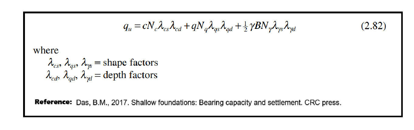
These two different values (3°, and 20°) from two different types of tests (CU, and CD) may lead to significantly different values as the Meyerhof's bearing capacity factors.
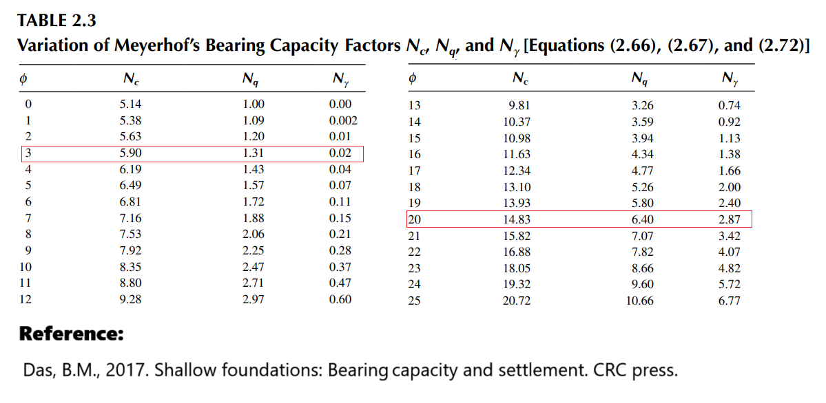
https://worksaccounts.com/wp-content/uploads/2020/08/Shallow-Foundations.pdf (PDF Page: 56/401)
Consequently, foundation dimensions derived from CU test results tend to be considerably smaller than those determined using CD test data.
However, the Consolidated Drained (CD) test is appropriate for determining the soil’s effective friction angle (φ′) in foundation design due to the following reasons:
- Foundations are typically subjected to long-term static loading conditions.
- Drainage occurs over time, especially in granular soils (e.g., sands and gravels) or stiff clays.
- The CD test reflects the soil’s behavior under fully drained conditions, which matches the in-service conditions of most shallow foundations.
- It avoids the potential overestimation of strength that can occur with undrained (total stress) tests in drained design scenarios.
To prevent the risk of unsafe foundation design resulting from inaccurate friction angles obtained through inappropriate testing methods, MkaPEB accepts the user defined values within the ranges uses values provided in established references for different USCS soil types.
|
Description |
USCS |
Soil friction angle [°] |
|
Reference |
|
|
|
|
min |
max |
Specific value |
|
|
Well graded gravel, sandy gravel, with little or no fines |
GW |
33 |
40 |
|
[1],[2], |
|
Poorly graded gravel, sandy gravel, with little or no fines |
GP |
32 |
44 |
|
[1], |
|
Sandy gravels - Loose |
(GW, GP) |
|
|
35 |
[3 cited in 6] |
|
Sandy gravels - Dense |
(GW, GP) |
|
|
50 |
[3 cited in 6] |
|
Silty gravels, silty sandy gravels |
GM |
30 |
40 |
|
[1], |
|
Clayey gravels, clayey sandy gravels |
GC |
28 |
35 |
|
[1], |
|
Well graded sands, gravelly sands, with little or no fines |
SW |
33 |
43 |
|
[1], |
|
Well-graded clean sand, gravelly sands - Compacted |
SW |
- |
- |
38 |
[3 cited in 6] |
|
Well-graded sand, angular grains - Loose |
(SW) |
|
|
33 |
[3 cited in 6] |
|
Well-graded sand, angular grains - Dense |
(SW) |
|
|
45 |
[3 cited in 6] |
|
Poorly graded sands, gravelly sands, with little or no fines |
SP |
30 |
39 |
|
[1], [2], |
|
Poorly-garded clean sand - Compacted |
SP |
- |
- |
37 |
[3 cited in 6] |
|
Uniform sand, round grains - Loose |
(SP) |
|
|
27 |
[3 cited in 6] |
|
Uniform sand, round grains - Dense |
(SP) |
|
|
34 |
[3 cited in 6] |
|
Sand |
SW, SP |
37 |
38 |
|
[7], |
|
Loose sand |
(SW, SP) |
29 |
30 |
|
[5 cited in 6] |
|
Medium sand |
(SW, SP) |
30 |
36 |
|
[5 cited in 6] |
|
Dense sand |
(SW, SP) |
36 |
41 |
|
[5 cited in 6] |
|
Silty sands |
SM |
32 |
35 |
|
[1], |
|
Silty clays, sand-silt mix - Compacted |
SM |
- |
- |
34 |
[3 cited in 6] |
|
Silty sand - Loose |
SM |
27 |
33 |
|
[3 cited in 6] |
|
Silty sand - Dense |
SM |
30 |
34 |
|
[3 cited in 6] |
|
Clayey sands |
SC |
30 |
40 |
|
[1], |
|
Calyey sands, sandy-clay mix - compacted |
SC |
|
|
31 |
[3 cited in 6] |
|
Loamy sand, sandy clay Loam |
SM, SC |
31 |
34 |
|
[7], |
|
Inorganic silts, silty or clayey fine sands, with slight plasticity |
ML |
27 |
41 |
|
[1], |
|
Inorganic silt - Loose |
ML |
27 |
30 |
|
[3 cited in 6] |
|
Inorganic silt - Dense |
ML |
30 |
35 |
|
[3 cited in 6] |
|
Inorganic clays, silty clays, sandy clays of low plasticity |
CL |
27 |
35 |
|
[1], |
|
Clays of low plasticity - compacted |
CL |
|
|
28 |
[3 cited in 6] |
|
Organic silts and organic silty clays of low plasticity |
OL |
22 |
32 |
|
[1], |
|
Inorganic silts of high plasticity |
MH |
23 |
33 |
|
[1], |
|
Clayey silts - compacted |
MH |
|
|
25 |
[3 cited in 6] |
|
Silts and clayey silts - compacted |
ML |
|
|
32 |
[3 cited in 6] |
|
Inorganic clays of high plasticity |
CH |
17 |
31 |
|
[1], |
|
Clays of high plasticity - compacted |
CH |
|
|
19 |
[3 cited in 6] |
|
Organic clays of high plasticity |
OH |
17 |
35 |
|
[1], |
|
Loam |
ML, OL, MH, OH |
28 |
32 |
|
[7], |
|
Silt Loam |
ML, OL, MH, OH |
25 |
32 |
|
[7], |
|
Clay Loam, Silty Clay Loam |
ML, OL, CL, MH, OH, CH |
18 |
32 |
|
[7], |
|
Silty clay |
OL, CL, OH, CH |
18 |
32 |
|
[7], |
|
Clay |
CL, CH, OH, OL |
18 |
28 |
|
[7], |
|
Peat and other highly organic soils |
Pt |
0 |
10 |
|
[2], |
|
|
|
|
|
|
|
https://www.geotechdata.info/parameter/angle-of-friction
Refrences
1. Swiss Standard SN 670 010b, Characteristic Coefficients of soils, Association of Swiss Road and Traffic Engineers Swiss Standard SN 670 010b, Characteristic Coefficients of soils, Association of Swiss Road and Traffic Engineers
2. JON W. KOLOSKI, SIGMUND D. SCHWARZ, and DONALD W. TUBBS, Geotechnical Properties of Geologic Materials, Engineering Geology in Washington, Volume 1, Washington Division of Geology and Earth Resources Bulletin 78, 1989, Link
3. Carter, M. and Bentley, S. (1991). Correlations of soil properties. Penetech Press Publishers, London.
4. Meyerhof, G. (1956). Penetration tests and bearing capacity of cohesionless soils. J Soils Mechanics and Foundation Division ASCE, 82(SM1).
5. Peck, R., Hanson,W., and Thornburn, T. (1974). Foundation Engineering Handbook. Wiley, London.
6. Obrzud R. & Truty, A.THE HARDENING SOIL MODEL - A PRACTICAL GUIDEBOOK Z Soil.PC 100701 report, revised 31.01.2012
7. Minnesota Department of Transportation, Pavement Design, 2007
Created with the Personal Edition of HelpNDoc: Why Microsoft Word Isn't Cut Out for Documentation: The Benefits of a Help Authoring Tool